


发布时间:2025-12-29
A screw mechanism is the most commonly used solution for converting rotary motion into linear motion. A screw motor directly connects the motor shaft to the screw (or uses a hollow threaded shaft) to drive the rotation of the thread. For screw motors, we are primarily concerned with two relationships: (1) how axial speed relates to motor rotational speed, and (2) how axial push/pull force correlates with the motor’s output torque. Below, we analyze these relationships.
1. Speed Transmission
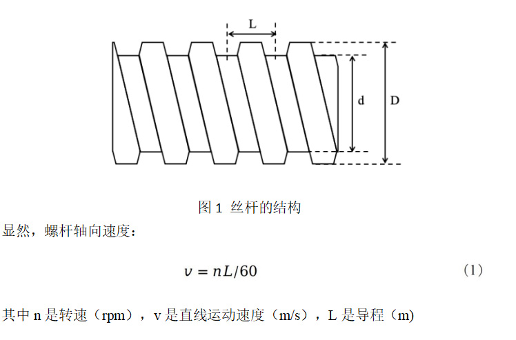
As shown in Figure 1, the lead L of a screw is the axial distance the nut travels when the screw rotates one full turn. In a single-start thread, the lead L equals the pitch.
2. Force Transmission
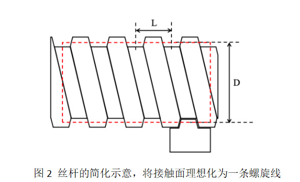
In scenarios where the screw drives the nut, force is transmitted through the threaded contact surface between the nut and the screw. For calculation convenience, we assume this contact surface is concentrated along a single line—specifically, a helical line with pitch L wrapped around a cylinder whose diameter lies between the screw’s minor (inner) and major (outer) diameters. This diameter is known as the pitch diameter (or mean diameter), as illustrated in Figure 2.
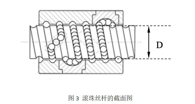
For ball screws, the contact between balls and grooves is linear. The outer diameter of the ball screw corresponds to the pitch diameter of the T-threaded screw described above (Figure 3).
It can be observed that when the external thread of the screw moves downward, the nut (represented by a green triangular block) experiences a rightward thrust force (as shown in the upper part of Figure 4).
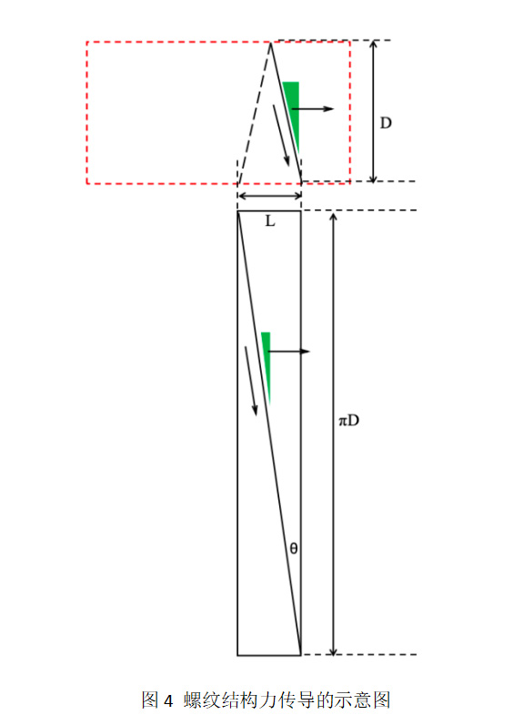
First, imagine unwrapping the cylindrical surface containing the thread (Figure 4). The thread then becomes an inclined plane, forming an angle θ with the radial plane of the thread. This angle is called the lead angle (or helix angle).
Clearly,

Further rotating the model from Figure 4 clockwise by 90° yields the configuration in Figure 5. When the screw rotates, it can be viewed as an inclined plane A pushing an object B upward along the slope, while object B is constrained to move only vertically (corresponding to the real-world case where the nut cannot rotate).
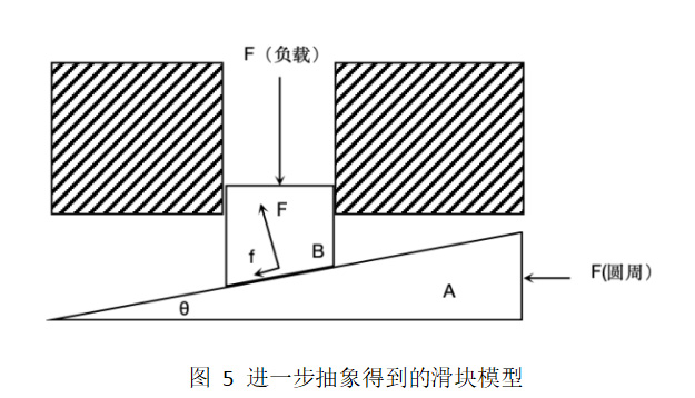
In this model, object A experiences a horizontal force to the left—this is the driving (circumferential) force F(circum) applied to the outer surface of the screw. In practice, this force acts tangentially at that point on the screw.
Object B (i.e., the nut) is subjected to three forces:
(1) A load reaction force F opposing motion (downward in the figure);
(2) A normal force F(normal) from the contact surface with A, acting perpendicular to the surface (upward);
(3) A friction force f exerted by A, opposing motion (down and to the right in the figure), proportional to the normal force:
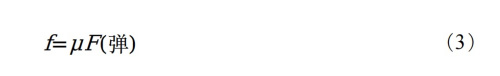
where μ is the dynamic friction coefficient between the two surfaces.
The friction force f and normal force F(normal) also act on object A, but in opposite directions.
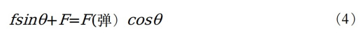
For a system in equilibrium, analyzing forces on B in the vertical direction gives:
Analyzing forces on A in the horizontal direction:

The torque of the screw is:

Combining Equations (2)–(5) and eliminating F(normal), F(circum), and f yields:
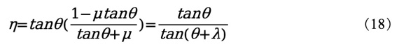
The efficiency η of screw transmission is defined as output work divided by input work:
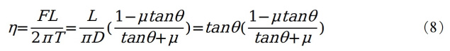
For T-threaded screws, sliding friction occurs between threads, with typical friction coefficients ranging from 0.1 to 0.5 (see Table 1). The lead angle θ usually falls between 5° and 10°, resulting in an efficiency of approximately 20%–30%.
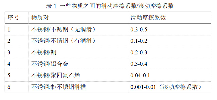
For ball screws, the rolling friction coefficient is very low—typically between 0.001 and 0.01—and the lead angle θ is generally 10°–20°. Since both μ and tanθ are small, the term μ·tanθ in the efficiency formula approaches zero, allowing the efficiency to be approximated as:
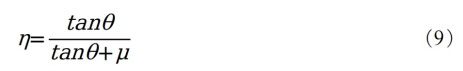
Thus, ball screw efficiency can easily exceed 90%.
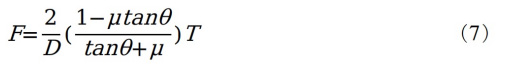
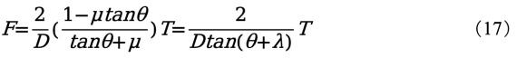
Conversely, if the transmission efficiency η is known, the axial thrust force of the screw can be calculated as:
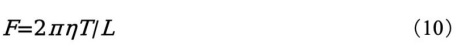
For example, if a T-threaded screw has an efficiency of 30%, a lead of 10 mm, and the motor input torque is 1 Nm, the resulting thrust force is 188 N. Under identical conditions, a ball screw with a 10 mm lead would produce a thrust force of up to 565 N.
Regarding the friction angle λ:
In the above model, suppose the driving force on the screw suddenly disappears (i.e., the leftward circumferential force F(circum) on A vanishes). The net horizontal force on A (taking left as positive) becomes:

At a certain critical value of θ, the screw is driven backward at constant speed solely by the load force. This specific angle θ is defined as the friction angle λ. At this point, the friction force is:
Since F(A) = 0, we have:

That is:

Or equivalently:

Clearly, when the friction angle λ equals the lead angle θ, the screw can be driven backward at constant speed by the load alone.
If λ < θ, the net horizontal force on A is:

This force is negative, meaning the resultant force points to the right, causing the screw to rotate backward.
However, if λ > θ, object A remains stationary—the static friction force and normal force balance each other horizontally. This condition is known as “self-locking.” Therefore, the self-locking condition for a screw mechanism is λ > θ. From Table 1, we know that ball screws have friction coefficients below 0.01, corresponding to friction angles less than 1°, which are inevitably smaller than θ. Hence, ball screws cannot self-lock. For standard T-threaded screws, assuming μ = 0.2, the friction angle is approximately 11°. To achieve self-locking, the lead angle θ must be less than 11°.
Substituting λ into the thrust force equation (7) yields:
Substituting into the efficiency equation gives:
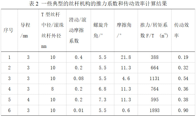
Using typical parameter values in these formulas allows us to calculate the thrust coefficient and transmission efficiency for common screw mechanisms, as summarized in Table 2.
With a solid understanding of the principles of screw transmission, selecting the right motor for your screw-driven mechanism will no longer be a challenge!